

I was one of the people in the latter group, continuously annoyed by people who don't understand the orders of magnitude of difference in computing power between a Redstone Computer (they are on par with 1930's technology) and a modern computer. After a fresh session of apoplectic rage however, I began to ponder: "What sort of program could you feasibly run on a Redstone Computer that would still retain the essence of Minecraft?" And thus a dream was born.
That was 3 months ago. After months of planning and sporadic construction work, I have finally completed this great and grand project which I intend to be my "Magnum Opus". I have made "Minecraft in Minecraft", or "Mini-Minecraft".
Features:
-2D Graphics!
-8x8 Pixel Screen
-64 bits of Landscape Data
-Blinking Lights!
-Directional Control Interface
-Solid Terrain
-Gravity
-Moderate Signal Latency (4,000ms)
-Color-Coded Circuitry!
And now to show that I'm not just full of ****, I give you screenshots:
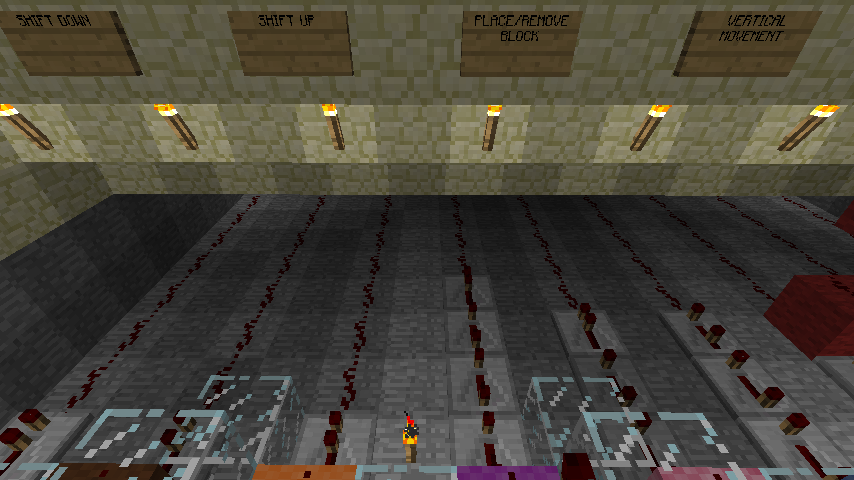
Display viewed from control-box
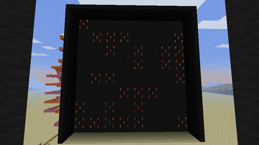
Here you're staring at the crazed mish-mash of all the terrain created/destroyed in my debugging attempts. Player position is not visible, since that square is currently OFF in its blink-cycle.
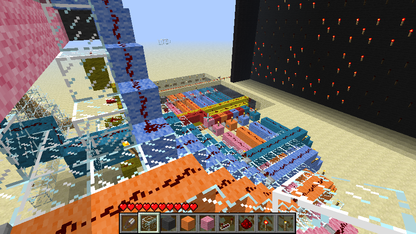
Display Side-View
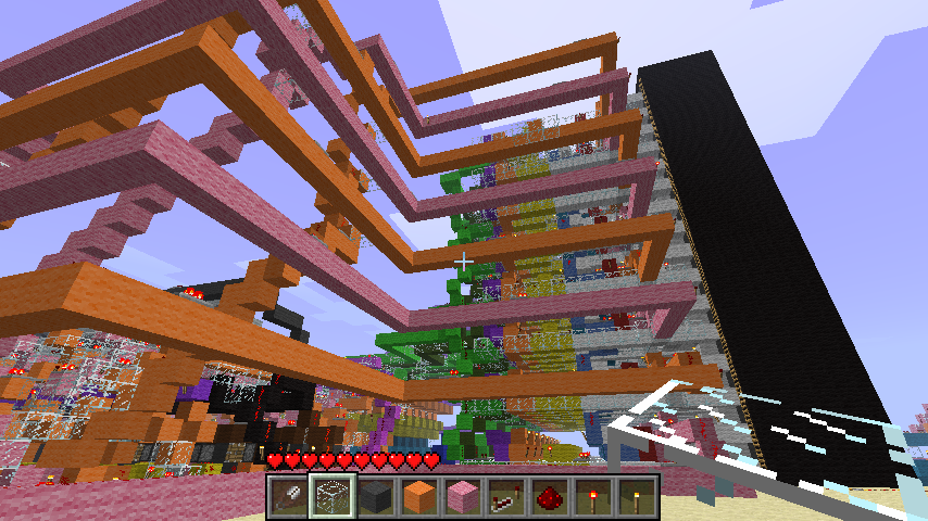
The orange and pink lines are carrying the Vertical Position data from its register to the display. The sharp-eyed will notice that there is a torch lit on right side of the middle pink line. That's the current height of the player. I placed those torches there for debugging purposes when I was having problems with data corruption.
High view of back of Display
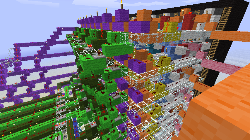
Light and Dark Green helixes carry new data to the Display, one Bit per column. Purple lines in the background carry the "Write" command to an individual Row to update its D Flip-Flops when a block there is placed or removed.
Guts of the machine
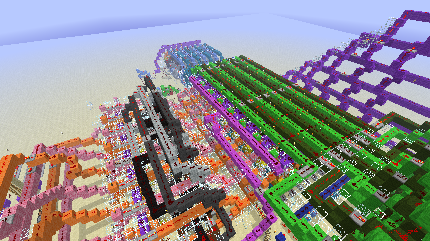
Here you see all the parts of the machine that do the actual calculations. Underneath the green lines is the 64 bits of RAM (the green lines are its input) that store the terrain information for calculations. In Blue at the far end are the Horizontal positional controls which both keep track of the player's horizontal position and govern interaction with blocks. The Gray stuff to the left is the circuitry needed for the "Jump" command, and underneath it is the rest of the Vertical positional controls.
Control-Bits
Here you can see 4 of the 9 Control-Bits that govern the machine. Combining "Shift Up" with "Place/Remove Block" results in the block above your current position toggling between ON and OFF. Note the long chains of Repeaters on some lines: It was necessary to introduce carefully tuned signal-delays to ensure that the Positional/Terrain actions don't happen until they have already been pointed to the right location. Getting the signal-delays synchronized like this took many hours of frustrating debugging even after I thought I was "95% done!". Well, I'm done NOW.
Wires Leading to Command Decoder
Here you see the wires from the Control-Box going down to be converted into signals sent to the Control-Bits that actually govern the machine. Pink/Orange are Down/Up and Light Blue/Teal are Left/Right. They split into 2 lines in the decoder: one for Movement, the other for Block manipulation. The Red line is in charge of triggering an extra "Move Downward" command after every action you perform in order to simulate gravity. A solid block underneath you will prevent this downward motion.
Control Panel
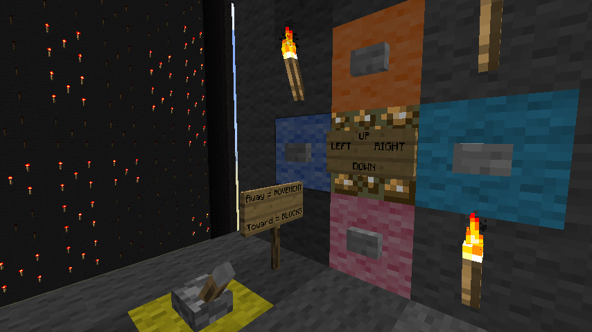
Here are the 5 controls that will let you move through the world. 4 directional controls and a switch to toggle between Movement and Block Placement/Removal. It's humbling to realize just how much work is required to convert a simple button-press into an executable command. It takes about 4 seconds for the effects of a button-press to be visible on the screen.
So, that's the sneak-preview of my machine.
I'm calling this a "Sneak Preview" because the real presentation is going to be the Youtube Video I'm planning on making which will show this thing in action, accompanied by mad laughter and melodrama and will get its own dedicated thread. My intention is for that video to go viral and explode the internets.
Oh, and also I'd like to give thanks to Conundromer for deciding not to beat me to completion of this project while I was on vacation, even though he probably could have if he'd set his mind to it(he's good).
If you think that "Minecraft in Minecraft" is totally awesome then feel free to +1 my Reputation. The higher it gets, the sooner my video comes out!
Edit: The video is out as of Aug 31st.
See this thread:http://www.minecraftforum.net/topic/590096-hans-lemurson-makes-minecraft-in-minecraft/
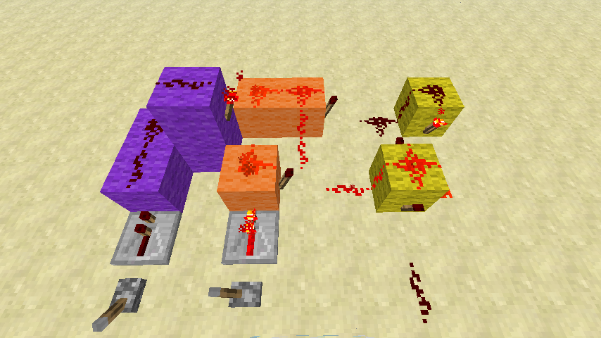
 Is the Memory Cell itself. It is an "RS NOR Latch", or "SR Latch" or "SR Flip-Flop". "SR" stands for "Set-Reset", referring to how data is entered into it. Its great strength is how small and compact it can be. Its great weakness is that it requires 2 different inputs in order to operate. :angry.gif:
 Fixes that problem. It holds a pair of torches which are always in the opposite state of one another. One acts as the "Set" input for the SR Latch, and the other acts as the "Reset" input. But most importantly, they themselves can be controlled by a single input. Unfortunately, this component also has a critical weakness: It writes to memory all the time, since at least one of the torches is on at any given time. An SR Latch by itself is a stable memory cell, but once you add the Orange torch-pair it's continually buffeted by the winds of change. Solution: Add another component. That'll fix things for sure!
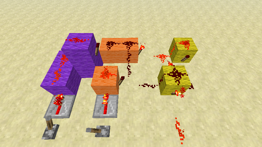
 Holds a carefully positioned torch which when ON, will shut-off both of the Orange Torches. While the Purple torch is ON, the Latch can rest in peace. Torch ON = Hold, Torch OFF = Write. Given this functionality, it is unsurprising that the Enable input controls this torch directly.
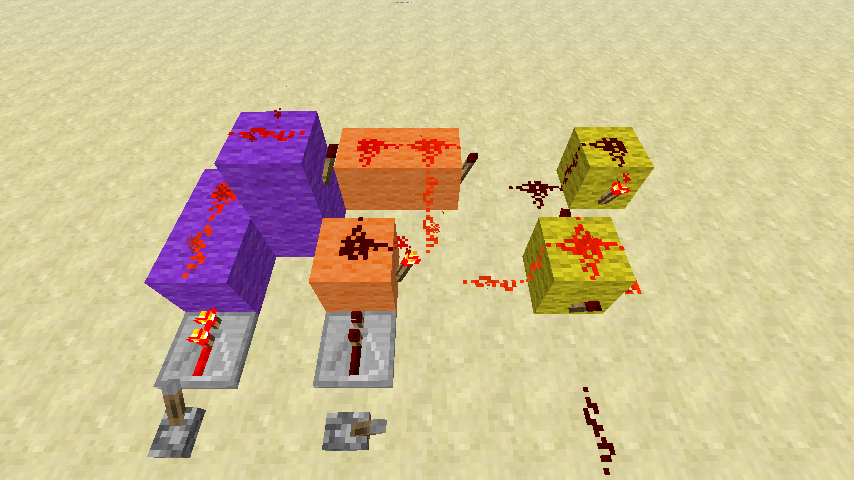
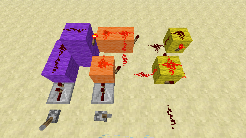
1
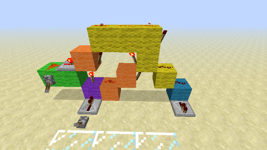
Or if you prefer a 1 block wide solution:
1